Schneider Electric
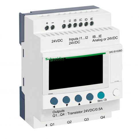
Zelio Logic modular smart relay Zelio Logic - 10 I O - 24 V DC - clock - display - SR3B102BD
Out of stock
SKU
SR3B102BD
More Information
| Attribute | Value |
|---|---|
| SKU | SR3B102BD |
| product certifications | GL, GOST, CSA, UL, C-Tick |
| relative humidity | 95-95 % without condensation or dripping water |
| ambient air temperature for storage | -40-70 °C |
| overvoltage category | III conforming to EN/IEC 60664-1 |
| pollution degree | 2 conforming to EN/IEC 61131-2 |
| ambient air temperature for operation | -20-40 °C in non-ventilated enclosure conforming to IEC 60068-2-1 and IEC 60068-2-2, -20-55 °C conforming to IEC 60068-2-1 and IEC 60068-2-2 |
| environmental characteristic | EMC directive conforming to EN/IEC 61000-6-2, EMC directive conforming to EN/IEC 61000-6-3, EMC directive conforming to EN/IEC 61000-6-4, EMC directive conforming to EN/IEC 61131-2 zone B, low voltage directive conforming to EN/IEC 61131-2 |
| current state 1 guaranteed | >= 1.2 mA (IB...IG used as discrete input circuit), >= 2.2 mA (I1...IA and IH...IR discrete input circuit) |
| voltage state 1 guaranteed | >= 15 V for I1...IA and IH...IR discrete input circuit, >= 15 V for IB...IG used as discrete input circuit |
| cycle time | 6-90 ms |
| output voltage | 24 V transistor output |
| range of product | Zelio Logic |
| product or component type | Relay & Power Supply |
| net weight | 0.22 kg |
| standards | EN/IEC 61000-4-12, EN/IEC 61000-4-4 level 3, EN/IEC 61000-4-6 level 3, EN/IEC 61000-4-3, EN/IEC 61000-4-2 level 3, EN/IEC 61000-4-5, EN/IEC 61000-4-11, EN/IEC 60068-2-6 Fc, EN/IEC 60068-2-27 Ea |
| range | Smart Relay |
| [Us] rated supply voltage | 24 V |
| analogue input type | common mode |
| short-circuit protection | with transistor output |
| immunity to microbreaks | 1 ms |
| repeat accuracy | +/- 2 % at 55 °C for analogue input circuit |
| input compatibility | 3-wire proximity sensors PNP for discrete input |
| backup time | 10 years at 25 °C |
| voltage state 0 guaranteed | <= 5 V for I1...IA and IH...IR discrete input circuit, <= 5 V for IB...IG used as discrete input circuit |
| analogue input range | 0...10 V, 0...24 V |
| conversion error | +/- 5 % at 25 °C for analogue input circuit, +/- 6.2 % at 55 °C for analogue input circuit |
| conversion time | smart relay cycle time for analogue input circuit |
| operating distance | 10 m between stations, with screened cable (sensor not isolated) for analogue input circuit |
| analogue input resolution | 8 bits |
| reverse polarity protection | with |
| [Ures] residual voltage | 2 V at state 1 transistor output |
| connections - terminals | screw terminals, 1 x 0.2...1 x 2.5 mm² (AWG 25...AWG 14) semi-solid, screw terminals, 1 x 0.2...1 x 2.5 mm² (AWG 25...AWG 14) solid, screw terminals, 1 x 0.25...1 x 2.5 mm² (AWG 24...AWG 14) flexible with cable end, screw terminals, 2 x 0.2...2 x 1.5 mm² (AWG 24...AWG 16) solid, screw terminals, 2 x 0.25...2 x 0.75 mm² (AWG 24...AWG 18) flexible with cable end |
| power dissipation in W | 8 W with extensions, 4 W without extension |
| output voltage limits | 19.2...30 V DC (transistor output) |
| operating altitude | 2000 m |
| IP degree of protection | IP20 (terminal block) conforming to IEC 60529, IP40 (front panel) conforming to IEC 60529 |
| tightening torque | 0.5 N.m |
| response time | <= 1 ms (from state 0 to state 1) for transistor output, <= 1 ms (from state 1 to state 0) for transistor output |
| load current | 0.5-0.625 A transistor output |
| supply voltage limits | 19.2-30 V |
| number of outputs | 4 transistor |
| discrete input voltage | 24 V DC |
| discrete input type | resistive |
| discrete input number | 6 conforming to EN/IEC 61131-2 type 1 |
| analogue input number | 4 |
| maximum permissible voltage | 30 V for analogue input circuit |
| input impedance | 12 kOhm for IB...IG used as analogue input circuit, 12 kOhm for IB...IG used as discrete input circuit, 7.4 kOhm for I1...IA and IH...IR discrete input circuit |
| disturbance radiated/conducted | class B conforming to EN 55022-11 group 1 |
| number or control scheme lines | 0-500 with FBD programming, 0-240 with ladder programming |
| clock drift | 12 min/year at 0-55 °C, 6 s/month at 25-25 °C |
| discrete input current | 4 mA |
| clock | with |
| local display | with |
| current state 0 guaranteed | <= 0.5 mA (IB...IG used as discrete input circuit), <= 0.75 mA (I1...IA and IH...IR discrete input circuit) |
| maximum supply current | 160 mA (with extensions), 50 mA (without extension) |
| maximum altitude transport | 3048 m |
| checks | program memory on each power up |
| LSB value | 39 mV for analogue input circuit |
| counting frequency | 1 kHz for discrete input |
| overload protection | with overload protection for transistor output |
Technical Documents


